
ESP32_Relay_X4_Modbus_v1.3
Device Type:
Electrical Standard:
Board:
Difficulty:Plug-n-flash (2/5)
Product Description
This is a 4-relay board, having 4 binary inputs and an RS485 interface based on ESP32. The inputs are optoisolated (mine came with TLP785GB with 4.7k resistors on inputs, making it safe to operate them around max 24V), with a common ground, independent from the board’s main ground. The RS485 transceiver is a SP3485E. Connectors are detachable.
I bought it from AliExpress.
Product Images
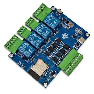
GPIO Pinout
According to Tasmota discussion:
| Function / Signal | ESP32 GPIO | ESP32 QFN Pin | Direction | Connected Hardware / Notes |
|---|---|---|---|---|
| RS485 TX | GPIO19 | Pin 31 | Output | UART TX -> SP3485 DI |
| RS485 RX | GPIO18 | Pin 30 | Input | UART RX <- SP3485 RO |
| RS485 Driver Enable | GPIO32 | Pin 8 | Output | SP3485 DE |
| RS485 Receiver Enable | GPIO32 | Pin 8 | Output | SP3485 RE (active LOW) |
| Relay 1 | GPIO23 | Pin 37 | Output | Relay output 1 |
| Relay 2 | GPIO5 | Pin 29 | Output | Relay output 2 |
| Relay 3 | GPIO4 | Pin 26 | Output | Relay output 3 |
| Relay 4 | GPIO13 | Pin 15 | Output | Relay output 4 |
| Digital Input 1 | GPIO25 | Pin 10 | Input | IN1 |
| Digital Input 2 | GPIO26 | Pin 11 | Input | IN2 |
| Digital Input 3 | GPIO27 | Pin 12 | Input | IN3 |
| Digital Input 4 | GPIO33 | Pin 9 | Input | IN4 |
| Status LED | GPIO15 | Pin 23 | Output | Usually inverted |
| PAD_TX2 | GPIO17 | Pin 28 | .. | no PSRAM |
| PAD_RX2 | GPIO16 | Pin 27 | .. | no PSRAM |
| PDAD_G12 | GPIO12 | .. | .. | .. |
| PDAD_G14 | GPIO14 | .. | .. | .. |
| PDAD_G21 | GPIO21 | .. | .. | .. |
| PDAD_G22 | GPIO22 | .. | .. | .. |
All pins are inverted. It also exposes GPIOs 12, 14, 21, 22 labeled appropriately on the board.
Basic Config
substitutions:  device_name: esp32-relay-x4_modbus-v1-3
esphome:  name: ${device_name}
esp32:  variant: esp32  framework:    type: esp-idf
logger:  baud_rate: 0
sensor:  - platform: uptime    name: Uptime
button:  - platform: restart    name: Reboot  - platform: safe_mode    name: Reboot in safe mode
# ==========================# RELAYS (OUTPUTS)# ==========================switch:  - platform: gpio    pin:      number: 23      inverted: true    name: "Relay 1"
  - platform: gpio    pin:      number: 5      inverted: true      ignore_strapping_warning: true    name: "Relay 2"
  - platform: gpio    pin:      number: 4      inverted: true    name: "Relay 3"
  - platform: gpio    pin:      number: 13      inverted: true    name: "Relay 4"
# ==========================# INPUTS (BINARY SENSORS)# ==========================binary_sensor:  - platform: gpio    pin:      number: 25      inverted: true    name: "Input 1"
  - platform: gpio    pin:      number: 26      inverted: true    name: "Input 2"
  - platform: gpio    pin:      number: 27      inverted: true    name: "Input 3"
  - platform: gpio    pin:      number: 33      inverted: true    name: "Input 4"
  # ==========================  # EXTRA PADS (RX2/TX2)  # ==========================  - platform: gpio    pin:      number: 16      inverted: true      mode: INPUT_PULLUP    name: "Pad RX2 as input"
  - platform: gpio    pin:      number: 17      inverted: true      mode: INPUT_PULLUP    name: "Pad TX2 as input"
# ==========================# RS485 (MODBUS) UART# ==========================uart:  rx_pin: 18 # RS485 RX  tx_pin: 19 # RS485 TX  flow_control_pin: 32 # RS485 DE  baud_rate: 9600
# ==========================# Status LED (system state)# ==========================status_led:  pin:    number: 15    inverted: true    ignore_strapping_warning: true